

Appearance
Signal Flow
Signal Flow is where you draw how the data cables run through the cabinets, per output port of the LED processor.
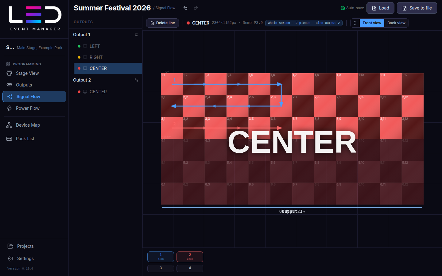
Set up an output
The left panel lists the outputs and their screens. Click an output (the ⚙ next to it) to set:
- Refresh rate (for example 60 Hz),
- Output count — the number of ports of the processor output,
- Backup controller (see below).
Signal output usage below the canvas shows every port and its load in pixels.
Draw a line
- Pick a screen in the left panel. A screen cut between several outputs is shown whole; the part fed by another output is dimmed and labelled.
- Pick a port number under the canvas — Drawing output 1.
- Click cabinet after cabinet in the order the cable runs (or drag across them). Right-click undoes the last segment. Esc finishes the line.
Line colours depend on the port number and on the processor, so port 1 of two processors never looks the same. Front view / Back view flips the drawing as seen from behind the screen.
Delete line mode: click a segment to delete it, Shift+click deletes the whole line.
Backup controller
Backup controller → Create adds a second device on the same cabling. You draw only the main signals; the Pack List counts both sets of cables. You can also drag an empty port onto an active one to make it its backup.
Export
Export PNG saves the drawing of one output, one screen, or everything at once. See Export.